Recently, one of my EdgeRouter – an ER6P – got bricked, without any reason. It was working fine and all of a sudden stopped working.
Using the serial console, the router was in a bootloop – failing to start.
SPI stage 1 bootloader
SPI ID: c2:20:17:c2:20
header found at offset 0x2000
Image 1.2: address: 0xffffffffc0000000, header length: 192, data length: 359416
Validating data...
Corrupted bootloader
Could not start next bootloader
...
At this stage, it was not possible to interract with the router, nor to follow any guide from ubiquiti to fix by doing TFTP recovery etc.
In order to repair the router, it is important to understand its architecture. The architecture I’m going to describe is valid for Cavium chip based devices, so at least ER6P, ER12, and probably ER4.
The router is composed of a SOC, the Cavium and a 4GB flash memory which contains the firmware. The SOC is not able to boot on a flash memory, as it requires some drivers, and a piece of software, that is not natively included in the SOC. For this reason, there is an additional memory composant: SPI flash. SPI – for serial peripheral interface – is slower than parallel flashes, but is a simple protocol that is supported by the SOC.
The role of this SPI flash (which is small – 64 mbits) is just to host the bootloaders. Yes, with a final “S”, because it is a multi-stage boot ! Another role of this SPI flash is to emulate an eeprom to store some settings, such as the serial number of the router, its MAC addresses…
The SPI flash is splitted into 3 partitions, and some free/unused space.
Here is the layout of this SPI memory:
boot0 and boot1 are not a failover that could be used in case of faulty upgrade or so – as it is sometimes seen, but as 2 levels of boot. The router first boots the boot0, then the boot1. Interestingly, both bootloaders seems to rely on UBoot, but the first one has far less modules/features integrated. For example, if boot1 is corrupted, you can obtain a shell in boot0, but it will not come with tftp server/clients compiled in etc.
In my case, both boot0 and boot1 got corrupted ! As such, I did not get any console access to the router, leaving me with 1 single remaining option: the hard way (“try harder”).
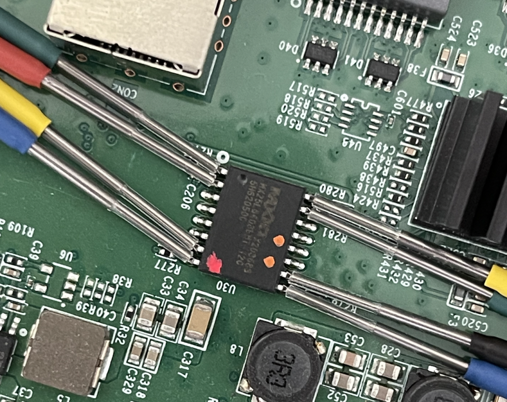
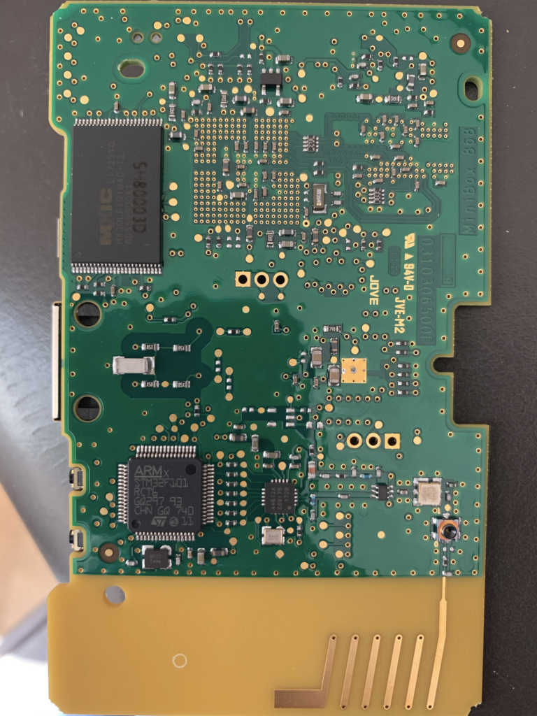
The hard way – in my case – was pretty simple: accessing the SPI flash in order to dump & flash it. I used my old good BusPirate friend, with Flashrom. Luckily, I did not have to unsolder the chip from the board to get it working.
I recommend using precision clamps / micro clamps that can be found on Aliexpress for example for few bucks.
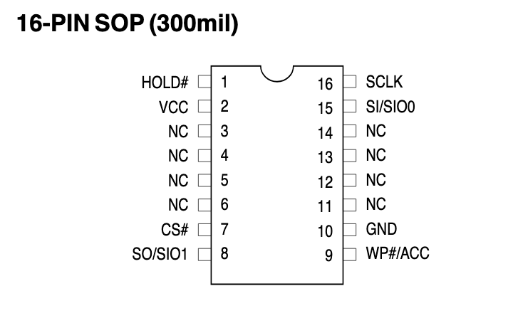
After having read carefuly the SPI datasheet (mx25l6405d), the pinout is obtained and can be connected to the buspirate.
Now that the pinout is known, just connect the correct buspirate probes to the SPI flash.
As you have to entirely re-write the flash – the first thing to do before anything else is to backup its content. Even if the bootloader is corrupted, the EEPROM partition might still be OK.
The previous command backups the content of the SPI flash to a file named backup-spi.bin. Note that I specified the chip type, to use correct SPI function codes.
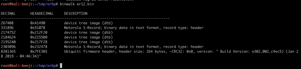
You now have the content of your flash. On a working router (the example below is with an ER12 SPI dump), it should looks like that:
As I said, there are 2 levels of bootloader, 0 and 1. If the bootloader 1 is corrupted, you can find its content in a firmware image from Ubiquiti, after extracting the squashfs image, in the root FS/etc/ubnt/bootloader.
The problem remains with bootloader 0: Ubiquiti does not provide its content – as the only way to re-flash it is to go with hardware probes.
At this stage, I only had an ER12 as a bootloader donor for my corrupted ER6P. As they both rely on Cavium SOC, I decided to give it a try to copy the ER12 bootloader to the ER6P. And it worked ! Well… the router booted, but it feeled like an ER12 instead of an ER6P. The ethernet ports were not correctly labelled, the LEDs were not correctly working etc. It was better than a brick, but not perfect. I still needed an ER6 dump.
I forgot to mention that to get a dump from a working router – there is an easier way than going with the buspirate : just use dd with /dev/boot0 / boot1 / eeprom.
Dumping from a working router:
dd if=/dev/boot0 of=/tmp/boot0.bin
Luckily, I found a working ER6 with a friend and could dump the bootloader 0. In case it could help other users – I decided to share them on github : https://github.com/blafois/edgerouter-spi-repair
Now, last step : before flashing back and bring back to life your router – you need to recompose the flash image. Remember the flash layout I presented earlier. You just need to keep your eeprom. Consider that your original dump is “backup-corrupted.bin”, and you get the dumps from “boot0.bin” and “boot1.bin”.
cat boot0.bin boot1.bin > repair-img.bin
# extract the eeprom from your backup - which resides in memory from 0040 0000 and 0041 0000
dd if=backup-corrupted.bin of=eeprom.bin bs=1 count=65536 skip=262144
cat eeprom.bin >> repair-img.bin
# now, just pad the image with some 0 (free space)
dd if=/dev/zero of=zeros.bin bs=1 count=4128768
cat zeros.bin >> repair-img.bin
# flash back image
flashrom -p buspirate_spi:dev=/dev/ttyUSB0 -w repair-img.bin -c MX25L6406E/MX25L6408E -V
At this stage, your router should be back to life 🙂
Edit: following comments from Cesar – here is the pinout for the Buspirate connection:
Lollipop Camera is designed to monitor babys. For details regarding the product, visit https://www.lollipop.camera/ website. It is quite affordable, and working pretty well.
The camera itself has a very good picture quality in night-vision or daylight. It comes with a mobile app to configure and use it.
For fun and integration, I was looking for reverse engineering, and integrate it into my existing home automation setup (OpenHAB).
RTSP Flow
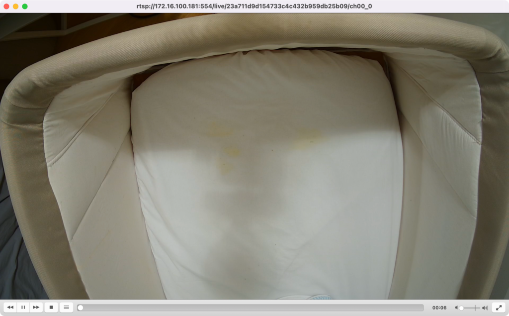
First good news: the camera supports and provides a direct RTSP flow! It is however not communicated officially. I discovered it by observing network traffic with Wireshark.
Only remark is that the address of the channel is not the same for all cameras, and has a variable part in the path:
Good news – it was easy to reverse and understand how to get this URL part!
When the camera is associated with an account during the setup phase – it gets associated a unique identifier. If you unregister and re-pair your camera, this ID will change. The number in the path is a simple MD5 hash of this pairing ID.
To compute the MD5 hash, one can use the following command under a Unix-like system:
echo -n '<id>' | md5sum
How to obtain this ID ? 2 solutions.
First solution, use the cloud API and retrieve the list of devices associated with your account.
Second solution, use the MQTT embedded broker (see next paragraph).
Once you get this unique ID, just get the MD5 hash of it and use your favorite tool such as VLC to access the video live feed:
The video itself is standard h264 encoded, full HD (1080p) and 30fps. It also has audio (AAC).
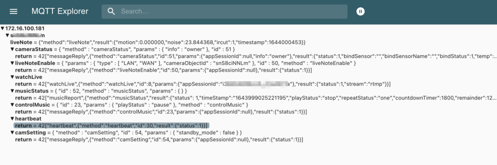
MQTT Broker
The camera hosts an MQTT broker on typical 1883 TCP port. One remark here – it is using TLS on the 1883 port – but without any authentication (I therefore wonder the goal of using TLS if no authentication is required…).
To connect to the broker and observe the trafic, you can either use a tool such as MQTT Explorer or mosquitto_sub in CLI. Mosquitto is slightly more complex as it forces you to provide a certificate authority for TLS – even if you don’t care about validating the certificate (use of –insecure).
I recommend, if you want to go with Mosquitto, to use stunnel to remove TLS layer:
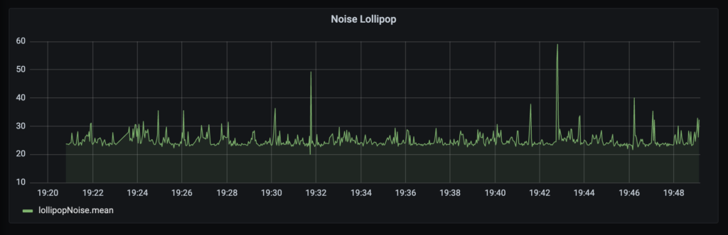
event_type: 3: noisy environment. with this event type, val is the noise level in DB.
General thoughts
I liked the fact that the camera is relatively opened, allowing the integration in existing installation. However, it is kind of insecure: getting IP connectivity to the camera, no password nor credential is required to access the video (including sound), nor control the camera through the MQTT broker.
As such, my recommendation would remain as usual: do not expose them to the internet, and if possible put all your IoT devices on a separate VLAN / SSID, with relatively strong isolation with your main network/VLAN/SSID.
My French ISP (Orange) uses DHCP messages with a CoS Priority of 6, otherwise they are not processed. So in order to avoid using the set top box provided by him, you can use an OpenWRT router which comes with UDHCP (part of Busybox).
Here is a small patch to support this.
$(busybox)/networking/udhcp/dhcpc.c
In function udhcp_raw_socket(int ifindex), line 1086:
+       /* Set Kernel Priority to 6 */
+       int val = 6;
+       setsockopt(fd, SOL_SOCKET, SO_PRIORITY, &val, sizeof(val));

        if (setsockopt_1(fd, SOL_PACKET, PACKET_AUXDATA) != 0) {
                if (errno != ENOPROTOOPT)
                        log1s("can't set PACKET_AUXDATA on raw socket");
        }
$(busybox)/networking/udhcp/packet.c
In function udhcp_send_raw_packet, line 123:
+       /* Set Kernel Priority to 6 */
+       int val = 6;
+       setsockopt(fd, SOL_SOCKET, SO_PRIORITY, &val, sizeof(val));
+       bb_info_msg("Packet priority set to %s", "6");

        memset(&dest_sll, 0, sizeof(dest_sll));
        memset(&packet, 0, offsetof(struct ip_udp_dhcp_packet, data));
        packet.data = *dhcp_pkt; /* struct copy */
In function udhcp_send_kernel_packet, line 213:
+       /* Set Kernel Priority to 6 */
+       int val = 6;
+       setsockopt(fd, SOL_SOCKET, SO_PRIORITY, &val, sizeof(val));

        /* If interface carrier goes down, unless we
         * bind socket to a particular netdev, the packet
         * can go out through another interface, eg. via
         * default route despite being bound to a specific
         * source IP. As such, bind to device hard and fail
         * otherwise. Sending renewal packets on foreign
         * interfaces makes no sense.
         */
        if (ifname) {
This article will mainly target people located in France, but who knows 🙂
Orange, a French ISP, provides FTTH with up to 2GB downling/600mbps uplink, but the usage (and rental…) of their set top box (aka Livebox) is mandatory.
As I’m using my own router (Ubiquiti EdgeRouter), the Livebox is useless to me, just taking some place and energy :-). The goal of this article is to explain how to remove it to use a router instead.
The Livebox 5 integrates an ONT. So in order to remove the LB5, I needed to find an external ONT. A friend gave me an “old” Huawei HG8010H, which is the one Orange used to provide with older Livebox versions.
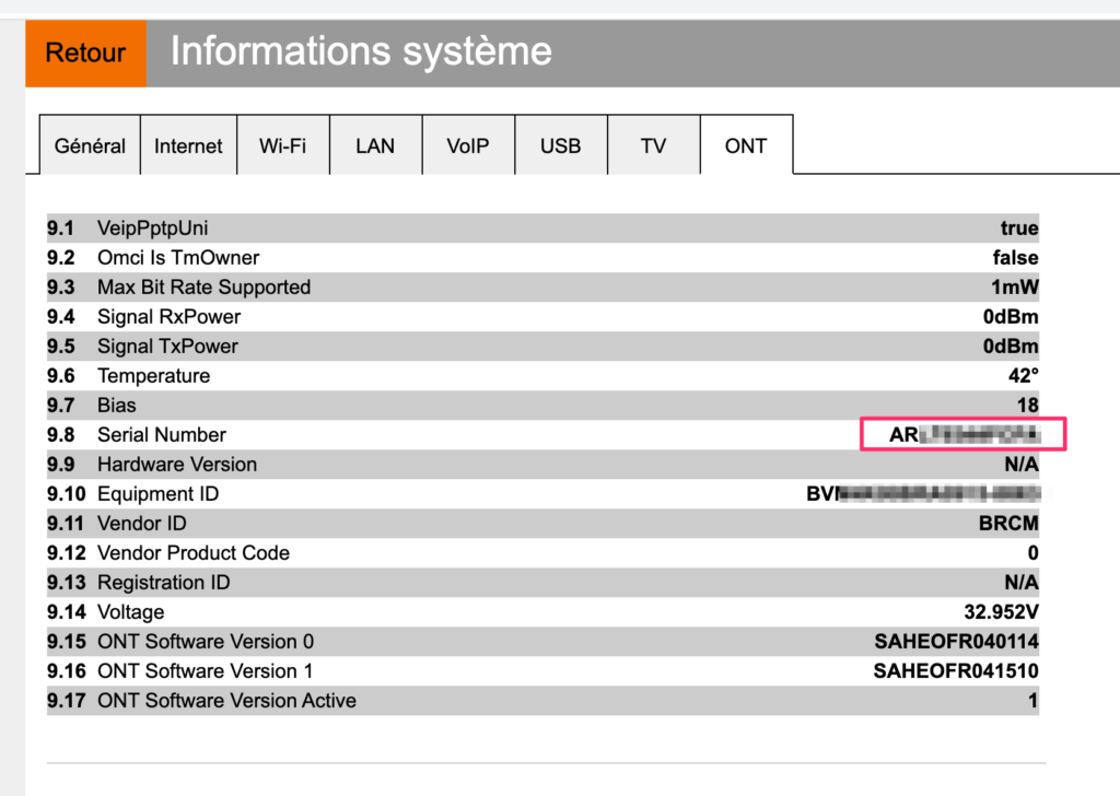
The first thing to do is to gate the ONT accepted on the optical network, commonly know as O5 state (“operation state” – https://www.mdpi.com/2076-3417/8/10/1934/pdf). To reach this state, the ONT must authenticate itself on the carrier network. Orange used to rely on the SLID (subscriber line ID), but this is no longer used. It now only relies on the serial number of the ONT. It means that is necessary to change the Serial Number of the new ONT by the allowed one (the Livebox). Getting the “allowed” SN is easy: just go on the Livebox administration page:
Getting the Serial Number of the ONT from Livebox 5
Setting the same SN in the new ONT is possible if the ONT is not in the ISP locked mode. I will not cover how to unlock an Orange-provided HG8010 ONT, this can be found on the web with keyboard “restorehwmode.sh” !
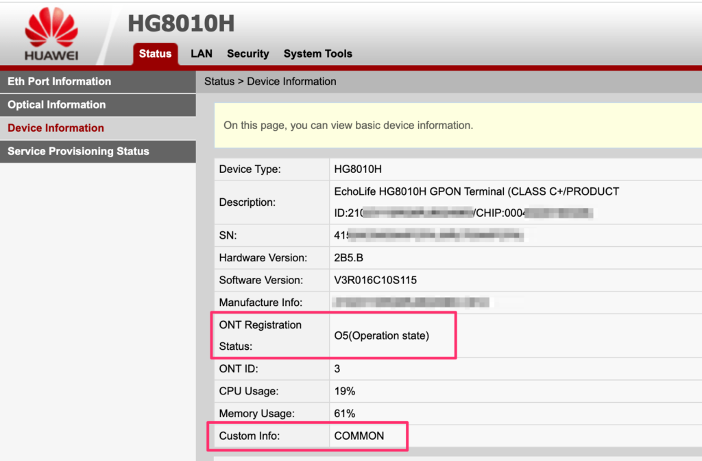
Once the Serial Number is changed on the ONT to simulate the Livebox, the fiber link should come up in O5 mode::
Now that the fiber link is up – the router must be configured to access.
Orange is using multiple VLANs (internet, TV, SIP…). I will just be covering the Internet access as I’m not using TV nor phone.
For Internet, the VLAN 832 should be used, using DHCP and the “option 90”, which is used to authenticate the subscriber.
The tricky detail is the following: DHCP packets should be sent with a VLAN priority set to 6 ! Without doing that, device won’t be able to authenticate to the network.
Before configuring the router, several things will be needed, such as the Mac Address of the Livebox and the authentication data. This can be calculated using a JavaScript tool, using the username & password provided by Orange (famous “fti/xxxx”). I chose a different option, which consists in gathering those information from the Livebox.
Feel free to use this simple Python script to obtain the information and generate the configuration for your EdgeRouter:
Last problem: the VLAN Priority 6. The router uses ISC-DHCP as DHCP client, which relies on raw sockets. As such, it bypasses the “egress policy” you could define on the router.
The only solution is to patch & recompile the ISC-DHCP to hardcode the VLAN priority.
Patching and re-compiling ISC-DHCP
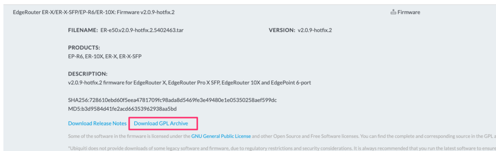
The easiest option is to use Docker! First of all, retrieve the package from Ubiquiti matching your router firmware version:
This archive includes all the package we need to recompile: edgeos-vyatta-dhcp.
Instanciate a Docker as follows:
docker run --rm -it debian:9.13 /bin/bash
Install necessary cross compilation toolchain:
apt-get update && apt-get install -y crossbuild-essential-mipsel vim
mkdir /data && cd /data
Copy the vyatta-dhcp3_4.1-ESV-R15-ubnt1+t5402460.dev.stretch.v2.0.9.24c30f9.tar.gz file to the /data in your docker:
For the version isc-dhclient-4.1-ESV-R15-P1, my patch file is:
--- a/common/discover.c
+++ b/common/discover.c
@@ -247,10 +247,6 @@ begin_iface_scan(struct iface_conf_list *ifaces) {
                log_error("Error creating socket to list interfaces; %m");
                return 0;
        }
-
-       /* Set Kernel Priority to 6 */
-       int val = 6;
-       setsockopt(ifaces->sock, SOL_SOCKET, SO_PRIORITY, &val, sizeof(val));

        memset(&lifnum, 0, sizeof(lifnum));
 #ifdef ISC_PLATFORM_HAVELIFNUM
diff --git a/common/icmp.c b/common/icmp.c
index ca857e0..6f97f67 100644
--- a/common/icmp.c
+++ b/common/icmp.c
@@ -95,10 +95,6 @@ void icmp_startup (routep, handler)
                        return;
                }

-               /* Set Kernel Priority to 6 */
-               int val = 6;
-               setsockopt(icmp_state -> socket, SOL_SOCKET, SO_PRIORITY, &val, sizeof(val));
-
 #if defined (HAVE_SETFD)
                if (fcntl (icmp_state -> socket, F_SETFD, 1) < 0)
                        log_error ("Can't set close-on-exec on icmp: %m");
diff --git a/common/lpf.c b/common/lpf.c
index 8111f38..fcf7db1 100644
--- a/common/lpf.c
+++ b/common/lpf.c
@@ -89,10 +89,6 @@ int if_register_lpf (info)
                log_fatal ("Open a socket for LPF: %m");
        }

-       /* Set Kernel Priority to 6 */
-       int val = 6;
-       setsockopt(sock, SOL_SOCKET, SO_PRIORITY, &val, sizeof(val));
-
        memset (&ifr, 0, sizeof ifr);
        strncpy (ifr.ifr_name, (const char *)info -> ifp, sizeof ifr.ifr_name);
        ifr.ifr_name[IFNAMSIZ-1] = '\0';
@@ -499,10 +495,6 @@ get_hw_addr(const char *name, struct hardware *hw) {
                log_fatal("Can't create socket for \"%s\": %m", name);
        }

-       /* Set Kernel Priority to 6 */
-       int val = 6;
-       setsockopt(sock, SOL_SOCKET, SO_PRIORITY, &val, sizeof(val));
-
        memset(&tmp, 0, sizeof(tmp));
        strcpy(tmp.ifr_name, name);
        if (ioctl(sock, SIOCGIFHWADDR, &tmp) < 0) {
diff --git a/common/raw.c b/common/raw.c
index b588f1b..a15f8ee 100644
--- a/common/raw.c
+++ b/common/raw.c
@@ -66,10 +66,6 @@ void if_register_send (info)
        if ((sock = socket (AF_INET, SOCK_RAW, IPPROTO_RAW)) < 0)
                log_fatal ("Can't create dhcp socket: %m");

-       /* Set Kernel Priority to 6 */
-       int val = 6;
-       setsockopt(sock, SOL_SOCKET, SO_PRIORITY, &val, sizeof(val));
-
        /* Set the BROADCAST option so that we can broadcast DHCP responses. */
        flag = 1;
        if (setsockopt (sock, SOL_SOCKET, SO_BROADCAST,
diff --git a/common/socket.c b/common/socket.c
index 8f94a63..3fe3d09 100644
--- a/common/socket.c
+++ b/common/socket.c
@@ -189,10 +189,6 @@ if_register_socket(struct interface_info *info, int family,
                log_fatal("Can't create dhcp socket: %m");
        }

-       /* Set Kernel Priority to 6 */
-       int val = 6;
-       setsockopt(sock, SOL_SOCKET, SO_PRIORITY, &val, sizeof(val));
-
        /* Set the REUSEADDR option so that we don't fail to start if
           we're being restarted. */
        flag = 1;
@@ -1178,10 +1174,6 @@ get_hw_addr(const char *name, struct hardware *hw) {
        }

  flag_check:
-       /* Set Kernel Priority to 6 */
-       int val = 6;
-       setsockopt(sock, SOL_SOCKET, SO_PRIORITY, &val, sizeof(val));
-
        if (lifr.lifr_flags & (IFF_VIRTUAL|IFF_IPMP)) {
                hw->hlen = sizeof (hw->hbuf);
                srandom((long)gethrtime());
Finally, recompile DHCLIENT.
cd /data/edgeos-vyatta-dhcp
make -f debian/rules configure
CC=mipsel-linux-gnu-gcc CPP=mipsel-linux-gnu-cpp ./configure --host=mipsel-linux-gnu --cache-file=config.cache
make
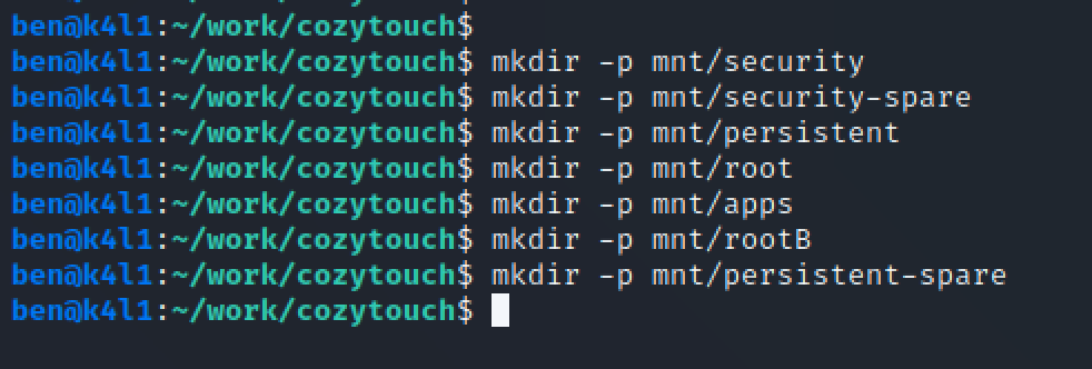
Here we are ! We now have a root access to the device – which is a good start. But what we were looking at – and our main motivation – is to access to all the sensors/probes/actuators values (in my case – for OpenHAB integration).
Having a root access, I started examining running processes, scripts, applications. The software bundle consists of a common bus – DBus – and multiple services communicating through the bus, all coded in LUA (compiled LUA). The LUA engine is a LUAJIT 2.0.
We will explore 2 different angles to interact with the Cozytouch data.
Option 1 – Interacting with the DBUS
The first thing is to enable the remote access to the bus, using TCP. By default, this is deactivated – for security reasons.
Warning: by doing this, you will introduce a security vulnerability to the CozyTouch as it will expose the DBUS System Bus without authentication. In my case, it is not a problem – the CozyTouch being isolated in my Home Automation airgapped VLAN.
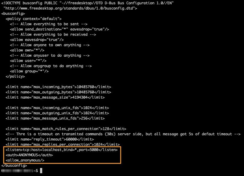
To enable DBUS over TCP, just alter the existing DBUS configuration:
/etc/dbus-1/system-local.conf
DBUS TCP configuration
Don’t forget that / is mounted as read-only by default. To alter any files, you’ll need to remount the / filesystem with read-write options:
$ mount -o remount,rw /
Now that you have access to the System DBUS, the first thing to do is listing of DBUS services:
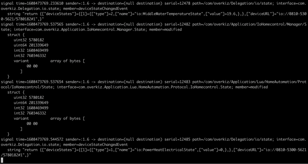
Periodically, the Bridge receives information (assuming that you have paired some devices with it through the mobile app).
DBus Listening/sniffing
Information is not encrypted – just coded. Reversing the coding will just require some extra reverse-engineering – and more widely – observation.
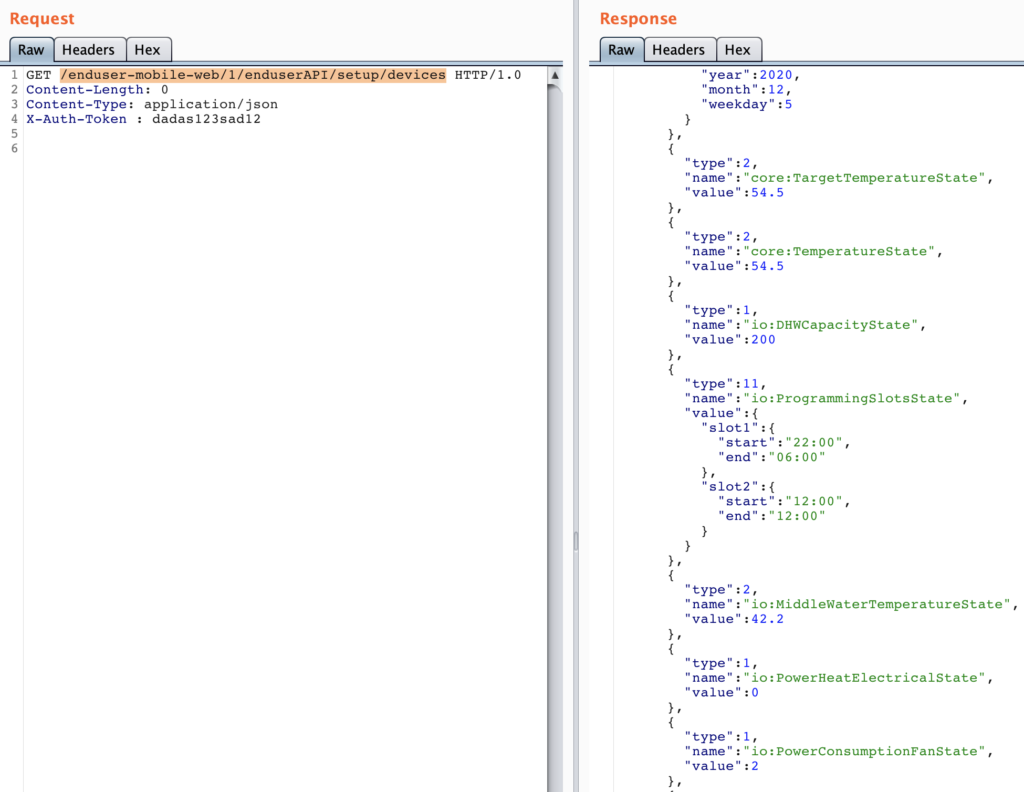
I chose using simple Python program/script to interact with the DBUS remotely. I will detail later the sensors/actuators capabilities – but keep in mind they only apply to my device (Atlantic AquaCozy).
Option 2 – Enabling the REST API
Having explored the device and reverse-engineering the Compiled LUA code – I figured out that the vendor has coded a REST API – but which is disabled by default. Sad.
The REST API is served by a webserver (lighttpd), which communicates with a LUA daemon over a unix file socket.
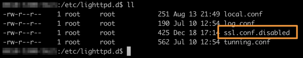
Step1: disable un-necessary lighttpd configuration (SSL). To achieve this, just rename /etc/lighttpd.d/ssl.conf to ssl.conf.disabled for example. Why ? Because SSL config needs a certificate & key which are not included, and disabling SSL is quicker than generating a keypair & cert!
Disabling SSL for lighttpd
Step2: starting lighttd:
$ /etc/init.d/lighttpd start
Step3: starting the LUA API Service
$ /usr/bin/luajit /apps/overkiz/local/bin/locald
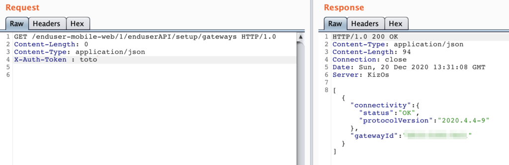
At this stage, the API is up and running and is accessible at http://<bridge ip>/enduser-mobile-web
Problems:
we don’t have API documentation
after few calls, you’ll realize that the API requires authentication (OAuth…)
Regarding the API documentation: decompile the LUA. Multiple LUA decompiles are available on Github. The resulting LUA is not perfect, but provides basics to be able to interact with the API.
Example of decompiled LUA – providing REST API information
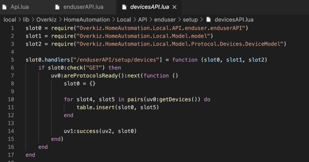
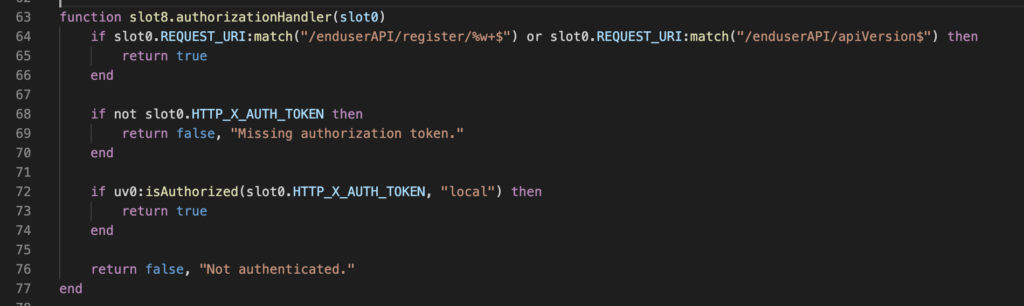
Now – the authentication part. More embarrassing, the code responsible of this is enduserAPI.lua:
Quickest and simple option, always return true to simulate a successful authentication. Problem: the LUA decompiled is not perfect and cannot be recompiled, it can just be used for reverse-engineering. Our option is patching the compiled LUA (hopefully – no code signature in place).
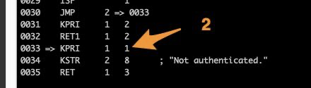
Reading a bit of LUA specifications (here or here for example), we learn that in LUA, the bool values are different from other languages:
0 means nil (null, not set)
1 means false
2 means true
Our function ends with instruction “RET 1 3”, which means returning the value which resides in “slot 1”. The slot 1 value is set 2 lines before, “KPRI 1 1”, which means value 1 (FALSE) is put in “slot 1”. What we just need to do is to replace this instruction by “KPRI 1 2”, in disassembly line 0033.
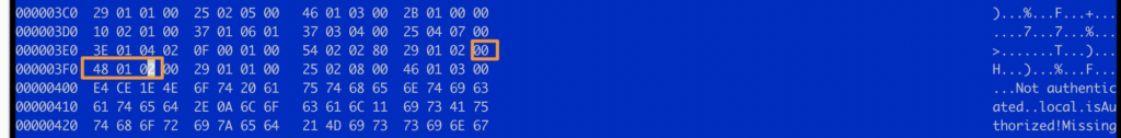
Unfortunately, once again, we cannot just alter the assembly code and re-assemble it. Not supported by LUAJIT. We will has such using an hex editor, and replace the value.
No miracle method to do that: multiple attempts to edit the files, and locate the right place, being assisted by LUA specs/docs. Fortunately, the LUA file is also small – which helps. You can also assist yourself with STRINGS (“not authenticated” for example, which are stored at the end of the function).
After patching the enduserAPI.lua, the daemon can be restarted, and the API used:
NB: you still need to provide the “X-Auth-Token” header, but the value is not checked.
The vendor was so kind to leave SSH installed on the build – DropBear – which is a common SSH daemon for embedded systems. We just need to enable it. If we look at runlevel 5 – SSH is disabled, and can easily be enabled, by simply renaming /etc/rc5.d/K06dropbear to /etc/rc5.d/S30dropbear.
No firewall port needs to be opened (simple NMAP test returns "port closed", and not "port filtered").
Last detail: there is no root password set! And a password (or a key) is necessary to login. Easier option: just alter /etc/shadow and replace:
Where $1$U5C8/RRe$jOaAuy.0o9R.eZOgHHYnI1 is Linux MD5 password hash for password “toor”.
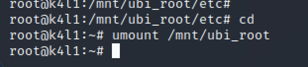
Now, umount the partition properly:
And dump the UBI root partition:
We know have a patched ROOT partition – and we need to flash-it back to the device. Because OpenOCD is not friendly – and it is always good to know multiple tools / options, we will use a different [advanced] technique to flash the Cozytouch, using a JLink probe.
Connect to the SoC using JLink
Start JLink:
root@raspberrypi4:~# /opt/JLink_Linux_V680_arm/JLinkExe
SEGGER J-Link Commander V6.80 (Compiled May 25 2020 17:09:50)
DLL version V6.80, compiled May 25 2020 17:09:30

Connecting to J-Link via USB...O.K.
Firmware: J-Link Pro V4 compiled Apr 16 2020 17:18:17
Hardware version: V4.00
S/N: 174402560
License(s): RDI, FlashBP, FlashDL, JFlash, GDB
IP-Addr: DHCP (no addr. received yet)
VTref=3.337V


Type "connect" to establish a target connection, '?' for help
J-Link>
The next step is to configure properly your interface:
Set the mode to JTAG:
J-Link>si 0
Selecting JTAG as current target interface.
Set the interface speed in adaptive mode (you can force a speed, but adaptative worked well)
J-Link>speed adaptive
Selecting adaptive clocking as target interface speed
Select the device type (SoC):
J-Link>device AT91SAM9G25
And finally, let the probe automatically detect the JTAG position
J-Link>JTAGConf -1,-1
Now that you are done with probe/tools configuration, let’s start the fun. Reset the device.
J-Link>r
Target connection not established yet but required for command.
Device "AT91SAM9G25" selected.


Connecting to target via JTAG
TotalIRLen = 4, IRPrint = 0x01
JTAG chain detection found 1 devices:
 #0 Id: 0x0792603F, IRLen: 04, ARM926EJ-S Core
CP15.0.0: 0x41069265: ARM, Architecture 5TEJ
CP15.0.1: 0x1D152152: ICache: 16kB (4*128*32), DCache: 16kB (4*128*32)
Cache type: Separate, Write-back, Format C (WT supported)
ARM9 identified.
Reset delay: 0 ms
Reset type NORMAL: Using RESET pin, halting CPU after Reset
CP15.0.0: 0x41069265: ARM, Architecture 5TEJ
CP15.0.1: 0x1D152152: ICache: 16kB (4*128*32), DCache: 16kB (4*128*32)
Cache type: Separate, Write-back, Format C (WT supported)
J-Link>
The Cozytouch is now instrumentable through JTag, with instruction pointer at address 0x00000000, and in halted state.
Understand the AT91 boot Sequence
From JLink, you can’t directly flash the NAND. NAND are not directly addressed in the CPU address space and need some drivers (as explained earlier when dumping).
It is mandatory to understand the AT91 boot sequence before moving forward.
From Texas Instrument Documentation
According to the documentation, the AT91SAM9G25 comes with SAM-BA, a boot-rom program. I managed to boot in SAM-BA mode, instrumenting and hijacking the boot sequence, but SAM-BA is not able to deal with NAND flash. It requires additional drivers which are not directly addressable with SAM-BA.
We want to boot to a well-known tool – U-Boot. It allows to manipulate the device, including dumping/flashing NAND. We cannot directly boot in U-Boot and must follow the vendor boot sequence. We will have to find & compile the AT91BootStrap & U-Boot.
As mentioned in the doc, the goal of the ROM code is to load the bootstrap from the 64k internal memory of the chip. We don’t need a complex bootstrap: we just want it to load NAND flash drivers, and pass it to the next stage (U-Boot).
As we don’t want to brick the device, we’ll not flash the NAND with our bootstrap and uboot, but just hijack the boot, copying it in live memory (RAM) with JTAG probe.
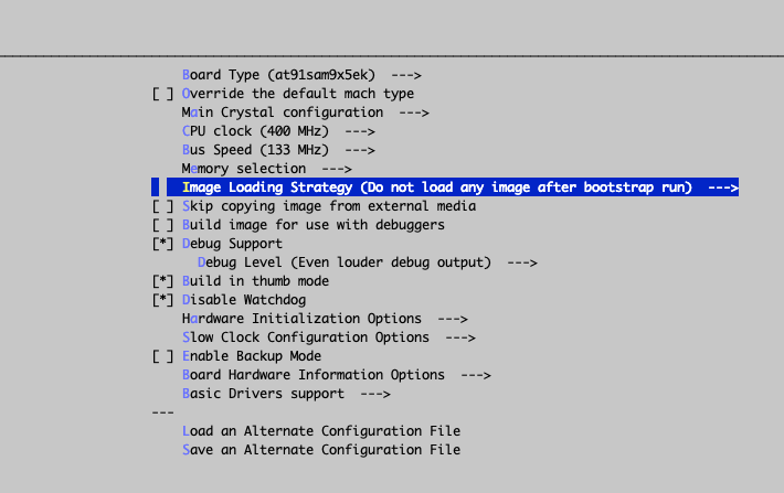
That being done, enter in the configuration options for the bootstrap:
make menuconfig
This will let you configure your perfect bootstrap. For me, the perfect bootstrap does… NOTHING: Image loading strategy -> do not load any image after bootstrap run.
Remember: the goal is not to take this board and run your own linux on it, but just to jailbreak it. At this stage, I’m just trying to figure how it works, and how is it made of.
AT91BootStrap Configuration Menu
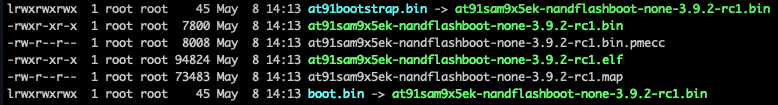
Once compiled, I obtained the following files:
We must now load this bootstrap. Easy.
First, we set a breackpoint at @0: As written in the documentation, once the ROM Code execution is done, it will execute the bootstrap which will be remapped at address 0. We will then set a breakpoint before executing the Bootstrap, write in the RAM the boostrap, then execute it:
J-Link>setbp 0 A
Breakpoint set @ addr 0x00000001 (Handle = 0)
J-Link>g
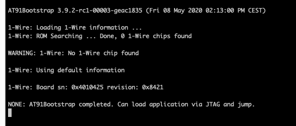
If you have the serial console plugged, you’ll see that the ROMCode as successfullly been executed:
ROM Code execution trace
The execution is now stopped at address 0, and the code at address 0 is the bootstrap provided by the Cozytouch vendor. Let’s overwrite it by our freshly compiled bootstrap:
Your AT91 SoC is now in a waiting state, with most drivers initialized, ready to move to second stage boot loading (Uboot).
Let’s copy the UBOOT executable code in the RAM – somewhere in the free memory (read the SoC documentation about RAM organization). Then, redirect the execution pointer at this address, and continue execution:
J-Link>loadbin /data/cozytouch/files/u-boot.bin 0x26f00000
Halting CPU for downloading file.
Downloading file [/data/cozytouch/files/u-boot.bin]...
O.K.
J-Link>setpc 0x26f00000
J-Link>g
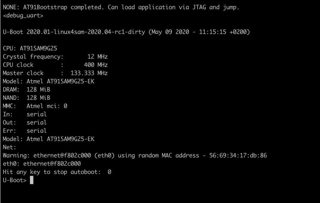
U-Boot loading
Welcome to U-Boot!
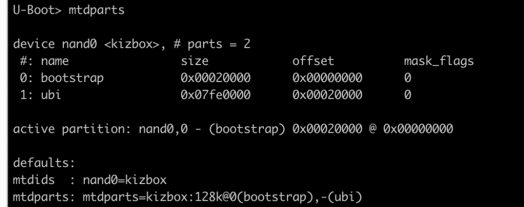
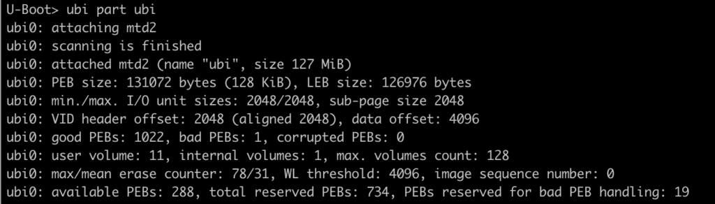
To confirm all our previous assumptions – we can for example list partitions:
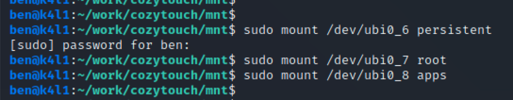
Now mount the 2nd partition as UBI:
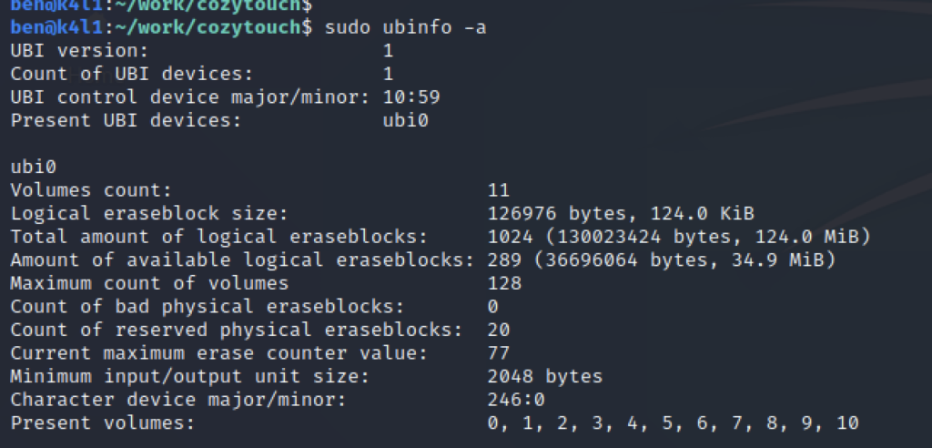
And finally, you can list all UBI partitions to confirm partition scheme discovered from the dump.
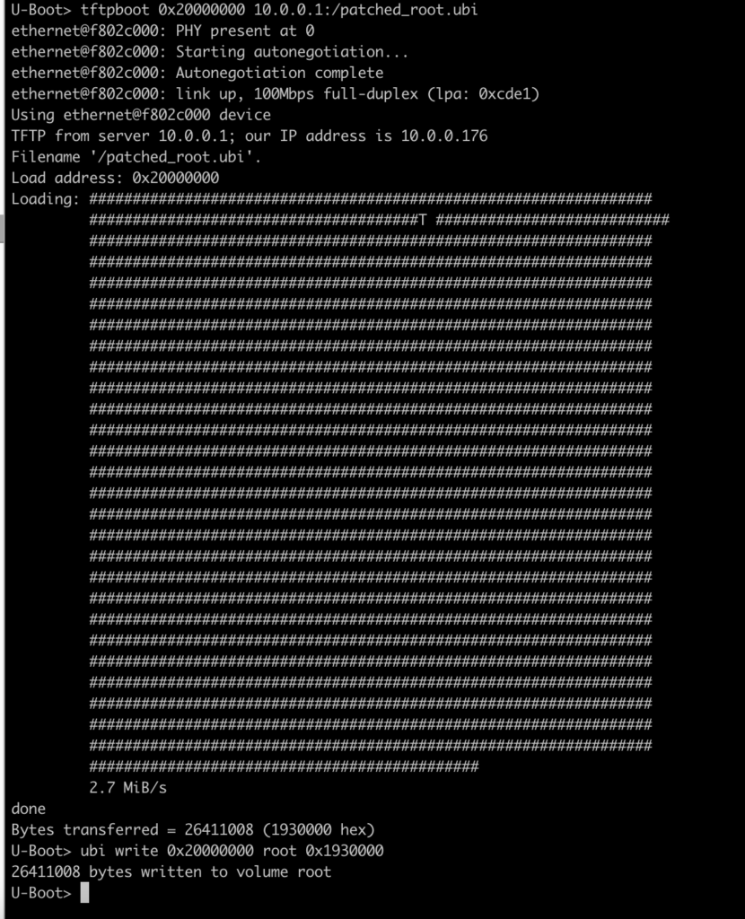
Flash the patched ROOT partition
Now that we have a working U-Boot and patched the ROOT partition, we want to flash it to the NAND, and check that we correctly rooted our device.
Install a TFTP daemon on your machine, as it will make your life easier to flash the Cozytouch with Uboot.
Once you have copied your file on the TFTP, load the new UBIFS for ROOT partition into memory:
Reboot the device (dont forget you have a breakpoint set with JLink! So if you don’t remove the BP nor hit “g”, the device won’t boot and wait for ages at PC 0x0).
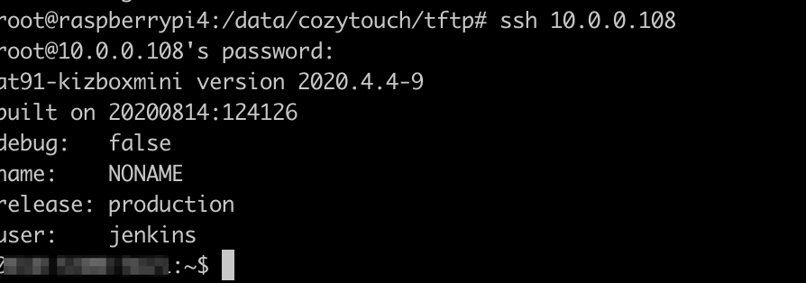
After couple of seconds – I assume you know how to find your Cozytouch on your LAN… And you can try SSH on it as root:
Login as root on the Cozytouch
Congratulations! You are now logged in as root on your Cozytouch !
After couple of days – I realized that the device was unrooted and SSH was not accessible anymore. I believe that the device has a watchdog routine, comparing the fingerprint/hash of the partition/firmware with an expected one. At the time of writing this article – I have not yet sorted out this “problem”.
OpenOCD (on chip debugger) is not very intuitive, and it’s the kind of tool that if you’ve not used it for a while.. you have to restart from scratch!
It comes with a collection of supported devices, but out of the box, the AT91SAM9G25 is not one of those. Thanks to the author of this blog, he published a configuration file for our chip and OpenOCD: https://jopee.wordpress.com/6lowpan-gateway/
Here is the file, all credits goes to the author of the blog.
################################
# Target:    Atmel AT91SAM9G25
######################################
if { [info exists CHIPNAME] } {
set AT91_CHIPNAME $CHIPNAME
} else {
set AT91_CHIPNAME at91sam9g25
}
source [find target/at91sam9.cfg]
# Set fallback clock to 1/6 of worst-case clock speed (which would be the 32.768 kHz slow clock).
adapter_khz 5
# Establish internal SRAM memory work areas that are important to pre-bootstrap loaders, etc.  The
# AT91SAM9G25 has one 32kByte SRAM area, starting at 0x00300000.
$_TARGETNAME configure -work-area-phys 0x00300000 -work-area-size 0x8000 -work-area-backup 1
set _FLASHTYPE nandflash_cs3
# Set reset type.  Note that the AT91SAM9G20-EK board has the trst signal disconnected.  Therefore
# the reset needs to be configured for “srst_only”.  If for some reason, a zero-ohm jumper is
# added to the board to connect the trst signal, then this parameter may need to be changed.
reset_config srst_only
adapter_nsrst_delay 200
jtag_ntrst_delay 200
# If you don’t want to execute built-in boot rom code (and there are good reasons at times not to do that) in the
# AT91SAM9 family, the microcontroller is a lump on a log without initialization.  Because this family has
# some powerful features, we want to have a special function that handles “reset init”.  To do this we declare
# an event handler where these special activities can take place.
scan_chain
$_TARGETNAME configure -event reset-init {at91sam9g25_reset_init}
$_TARGETNAME configure -event reset-start {at91sam9g25_reset_start}
# NandFlash configuration and definition
nand device nandflash_cs3 at91sam9 $_TARGETNAME 0x40000000 0xffffe014
at91sam9 cle 0 22
at91sam9 ale 0 21
at91sam9 rdy_busy 0 0xfffff800 5
at91sam9 ce 0 0xfffffA00 4
proc read_register {register} {
        set result “”
        mem2array result 32 $register 1
        return $result(0)
}
proc at91sam9g25_reset_start { } {
# Make sure that the the jtag is running slow, since there are a number of different ways the board
# can be configured coming into this state that can cause communication problems with the jtag
# adapter.  Also since this call can be made following a “reset init” where fast memory accesses
# are enabled, need to temporarily shut this down so that the RSTC_MR register can be written at slower
# jtag speed without causing GDB keep alive problem.
arm7_9 fast_memory_access disable
adapter_khz 2                   ;# Slow-speed oscillator enabled at reset, so run jtag speed slow.
halt                            ;# Make sure processor is halted, or error will result in following steps.
wait_halt 10000
#mww 0xfffffe08 0xa5000001       ;# RSTC_MR : enable user reset.
#mww 0xFFFFFE00 0xA500000B ;# Reset CPU
}
proc at91sam9g25_reset_init { } {
mww 0xfffffe44 0x00008000 ;# WDT_MR : disable watchdog.
# Enable the main 12 MHz oscillator in CKGR_MOR register.
# Wait for MOSCS in PMC_SR to assert indicating oscillator is again stable after change to CKGR_MOR.
mww 0xfffffc20 0x01370F01
while { [expr [read_register 0xfffffc68] & 0x01] != 1 } { sleep 1 }
echo 1
## PMC Clock generator PLLA register
# DIVA = 3
# PLLACOUNT = 0x3F
# MULA = 0xc7
# OUTA = 0
# PLLA Frequency = 12 MHz / DIVA * (MULA + 1) = 800MHz
mww 0xfffffc28 0x20C73f03
while { [expr [read_register 0xfffffc68] & 0x02] != 2 } { sleep 1 }
echo 2
        mww 0xfffffc30 0x00001300
        while { [expr [read_register 0xfffffc68] & 0x08] != 8 } { sleep 1 }
echo 3
# Set master system clock prescaler divide by 6 and processor clock divide by 2 in PMC_MCKR.
# Wait for MCKRDY signal from PMC_SR to assert.
# System Clock = 800 MHz / 6 = 133MHz
# CPU Clock = 800 MHz / 2 = 400 MHz
#
mww 0xfffffc30 0x00001302
while { [expr [read_register 0xfffffc68] & 0x08] != 8 } { sleep 1 }
echo 4
# Switch over to adaptive clocking.
adapter_khz 100000
# Enable faster DCC downloads and memory accesses.
arm7_9 dcc_downloads enable
arm7_9 fast_memory_access enable
### Configure NAND
#
mww 0xFFFFFA04 0xffffffff
mww 0xfffffa74 0x3fef
mww 0xfffffc10 0x00000008
mww 0xfffffa00 0x00000030
mww 0xfffffa10 0x00000010
mww 0xfffffa30 0x00000010
mww 0xFFFFEA30 0x00020002
mww 0xFFFFEA34 0x04040404
mww 0xFFFFEA38 0x00070007
mww 0xFFFFEA3c 0x00030003
# configure NAND PMECC
### DRAM Setup
#
#
#
# CCFG_EBICSA
# Configure DRAM on EBI CS 1
# Set low drive strength
mww 0xFFFFDF20 0x0102000A
        # 0. Enable DDR2 Clock
        mww 0xfffffc00 0x4
# DDRSDRC_HS
# Disable Anticipated read access
mww 0xffffe82c 0x04
# DDRSDRC_MD
# 16-bit databus
# DDR-2
# According to the datasheet this value SHOULD be 0x14 for 16-bit DDR2!
mww 0xffffe820 0x16
# DDRSDRC_CR
#
# 10 col bits
# 13 row bits
# CAS 3
mww 0xffffe808 0x100039
## DDRSDRC_TPR0
#
mww 0xffffe80c 0x21222226
## DDRSDRC_TPR1
#
mww 0xffffe810 0x2c81312
## DDRSDRC_TPR2
#
mww 0xffffe814 0x1372
## DDRSDRC_MR
mww 0xffffe800 0x01 ;# NOP
mww 0x20000000 0x00
sleep 1
mww 0xffffe800 0x01 ;# NOP
mww 0x20000000 0x00
mww 0xffffe800 0x02 ;# All banks pre-charge
mww 0x20000000 0x00
mww 0xffffe800 0x05 ;# Extended load mode register
mww 0x24000000 0x00
mww 0xffffe800 0x05 ;# Extended load mode register
mww 0x26000000 0x00
mww 0xffffe800 0x05 ;# Extended load mode register
mww 0x22000000 0x00
## DDRSDRC_CR
mww 0xffffe808 0x1000b9
# Reset DLL
mww 0xffffe800 0x03 ;# LMR
mww 0x20000000 0x00
mww 0xffffe800 0x02 ;# All banks pre-charge
mww 0x20000000 0x00
mww 0xffffe800 0x04 ;# Auto refresh
mww 0x20000000 0x00
mww 0xffffe800 0x04 ;# Auto refresh
mww 0x20000000 0x00
        # DDRSDRC_CR
        #
        # 10 col bits
        # 13 row bits
        # CAS 3
        mww 0xffffe808 0x100039
       mww 0xffffe800 0x03 ;# LMR
        mww 0x20000000 0x00
        mww 0xffffe808 0x100739
       mww 0xffffe800 0x05 ;# eLMR
        mww 0x22000000 0x00
        mww 0xffffe808 0x100039
       mww 0xffffe800 0x05 ;# eLMR
        mww 0x26000000 0x00
       mww 0xffffe800 0x00 ;# Normal
        mww 0x20000000 0x00
## DDRSDRC_RTR
mww 0xffffe804 0x411
mww 0xffffe82c 0x04
sleep 1
mww 0x20000000 0xdeadbeef
mdw 0x20000000
nand probe 0
}
Save this file in /usr/share/openocd/scripts/board/at91sam9g25.cfg
Now, you need to create an openocd.cfg file, describing your setup, which is mainly:
your probe
the board
your own routines
I’ll not go through all the steps to create the file – it took me a while! Find below the content of the file I used.
# Use JLink interface (/usr/share/openocd/scripts/interface/jlink.cfg) source [find interface/jlink.cfg]
# JLink requires a speed to be used by the probe. 0 means adaptive. adapter_khz 0
# JLink also requires to specify the transport type. Here we use JTAG transport select jtag
# Load the board config file for the at91 source [find board/at91sam9g25.cfg]
# My own initialization routine. Reset the device, and configure the NAND bank for access. proc reset_ben {} { reset halt adapter_khz 0
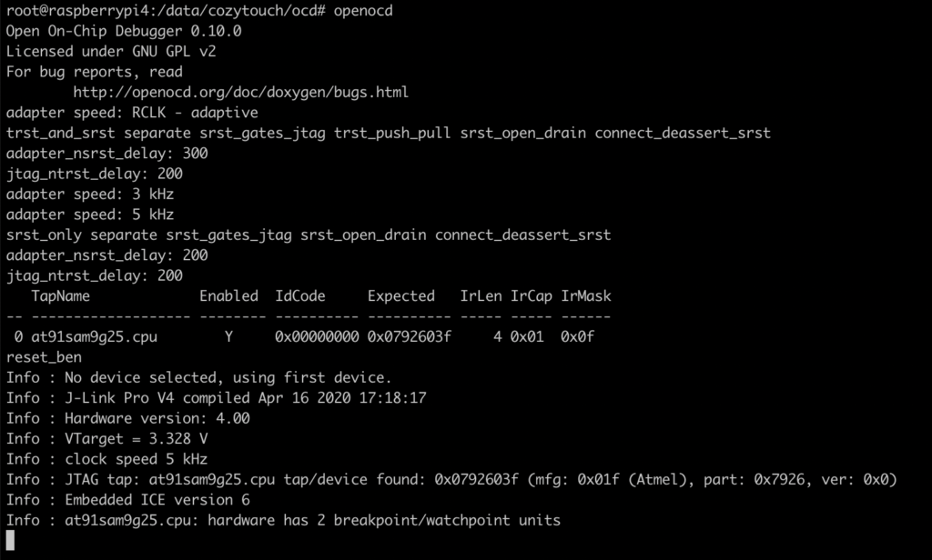
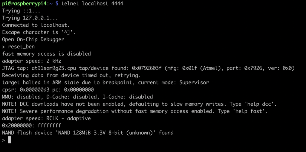
You can now simply start openocd. If everything goes right, you should see something like this:
Starting OpenOCD
You can now interact with OpenOCD, telnetting to the local port 4444, and start with my routine “reset_ben”:
Interacting with OpenOCD
The NAND flash device has been found and identified correctly. Great! We can now start dumping the NAND. For memory, here is the list of available NAND commands:
nand
NAND flash command group (command valid any time)
nand check_bad_blocks bank_id [offset length]
check all or part of NAND flash device for bad blocks
nand device bank_id driver target [driver_options ...]
defines a new NAND bank (configuration command)
nand drivers
lists available NAND drivers (command valid any time)
nand dump bank_id filename offset length ['oob_raw'|'oob_only']
dump from NAND flash device
nand erase bank_id [offset length]
erase all or subset of blocks on NAND flash device
nand info [banknum | first_bank_num last_bank_num]
print info about one or more NAND flash devices
nand init
initialize NAND devices (configuration command)
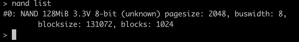
nand list
list configured NAND flash devices
nand probe bank_id
identify NAND flash device
nand raw_access bank_id ['enable'|'disable']
raw access to NAND flash device
nand verify bank_id filename offset
['oob_raw'|'oob_only'|'oob_softecc'|'oob_softecc_kw']
verify NAND flash device
nand write bank_id filename offset
['oob_raw'|'oob_only'|'oob_softecc'|'oob_softecc_kw']
write to NAND flash device
List available banks
Let’s start dumping! Here, it’s a bit up to you, but I prefer dumping with small lots of 1MB, which are 8 blocks of 131072. There are 1024 blocks, dumping with 1MB, it makes 128 dumps.
Dump a 1MB block
Ok… I’m not going to dump 1 by 1 by hand… so a quick python script to generate the dump instructions (there was probably a way to do it in OpenOCD…):
#!/usr/bin/python3

# 1MB Bloc size
dumpSize = 0x100000

# Number of blocks
blocks = 128

s = "nand dump 0 /data/cozytouch/2020_11_08-nand-dump/{0:04d}.bin 0x{1:x} 0x{2:x}"

for i in range(blocks):
    print(s.format(i,i*dumpSize,dumpSize))
Copy paste in your OpenOCD telnet window… and go grab a coffee ☕️ !
P.S. : I found that after dumping 2 blocks, the board became unstable. Quick [and dirty – but who cares] workaround: reset the board every 2 dumps:
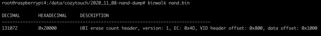
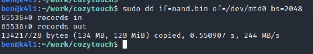
Now that you have dumped the 128 blocks of 1MB – its time to re assemble it and start analyzing it.
cat *.bin > nand.bin
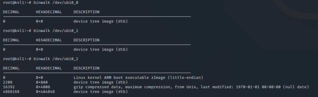
Favorite tool to start with… binwalk ! The output is not very verbose, but indicates that the NAND flash uses the UBI filesystem – which is common for NAND on embedded devices.
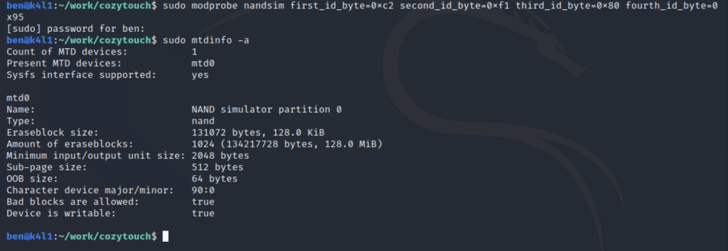
If we want to be able to work with the NAND image – and list and mount partition, one option is to emulate on our linux an MTD device. The various parameter describe flash size, block size, etc.
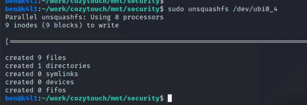
UbiFS partitions can be mounted straightforward – whereas the SquashFS needs to be extracted.
Now, mount each filesystem:
Mounting partitionsExtracting the SquashFS image
At this stage, you can start exploring the device file systems, and understand the logic. Looking at /etc/fstab from the root partition indicates that apps and persistent partitions are mounted in /apps and /persistent respectively:
/etc/fstab
By default, all the ports are closed on the device. What we want to do is be able to connect to the device first. What about enabling SSH ? read it in the next part !
The Cozytouch is an home automation gateway from the French manufacturer Atlantique/Thermor and also sold under the Sauter brand, depending on selling channel. They’re all identical, both from hardware and software perspective.
The Cozytouch brings the connectivity to various appliances (water boiler, heater…) and the Atlantic cloud (bridge). It allows users to control their appliance from a mobile app available on iOS/Android. Appliances and the bridge are communicating over a closed-source wireless protocol called IOHomeControl operating in the 868mhz band.
The bridge itself, the cloud and the protocols are closed-source and undocumented. The features and data accessible are also very limited. As such, in order to better integrate my water boiler in my home automation, I decided to root the device. 😈
Another option could be hacking the wireless protocol using an RTL/SDR, but if the crypto is well done, it is likely to be a very long way with little results.
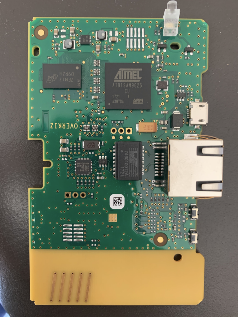
Dissassembly & PCB analysis.
The board is manufacturer/designed by Overkiz, a subsidiary of French manufacturer Somfy.
The board design is pretty simple. It is based on 2 SoC which seems to communicate through a simple UART.
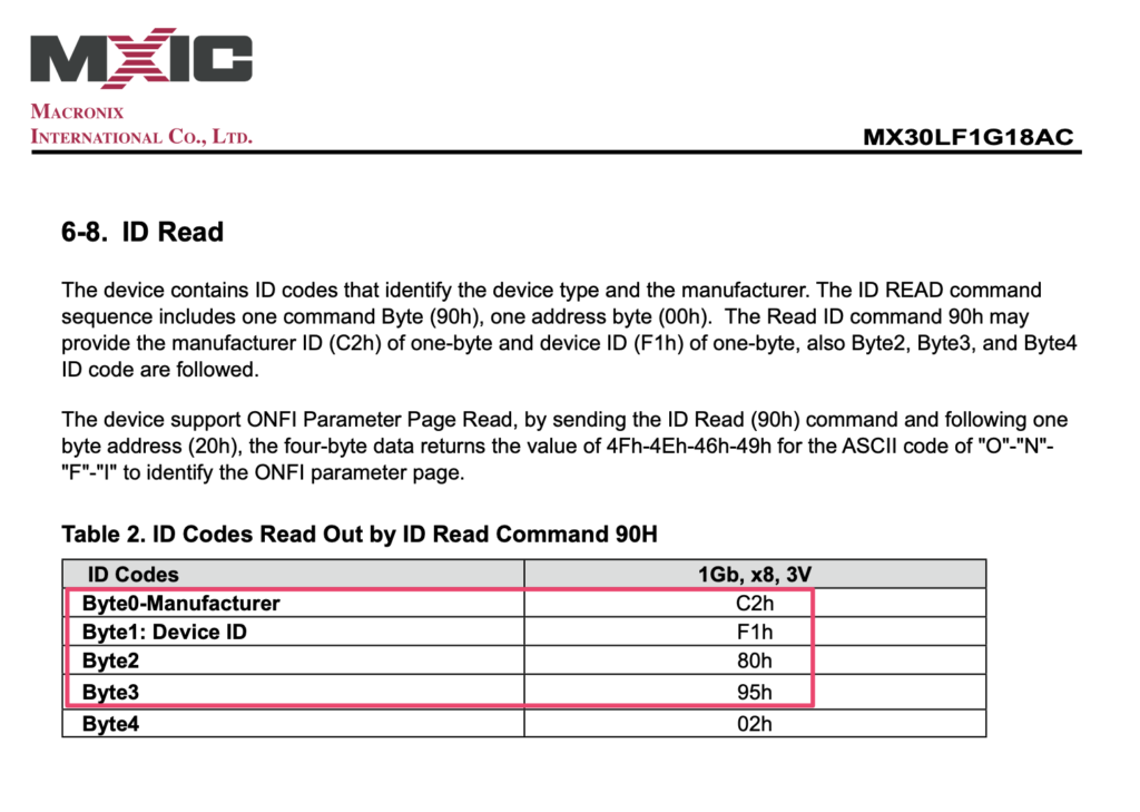
The first SoC, an Atmel AT91SAM9G25, is running the Linux system and in charge of edge-computing feature and communication with the cloud (no wifi – only ethernet). It is surrounded by a 1GB Nand Flash (MX30LF1G18AC) and a 1GB DDR2 RAM module (MT47H64M16NF-25E).
The second SoC, an STMicro ST32, is used exclusively for the radio communication (SDR). It will be found later once the OS is rooted, that this SOC can operate various protocols in various wavelength.
The pure software angle did not provide any way to get in the device. No open port, no upgrade protocol allowing MiTM, encryption made properly… No alternative: go the hard way!
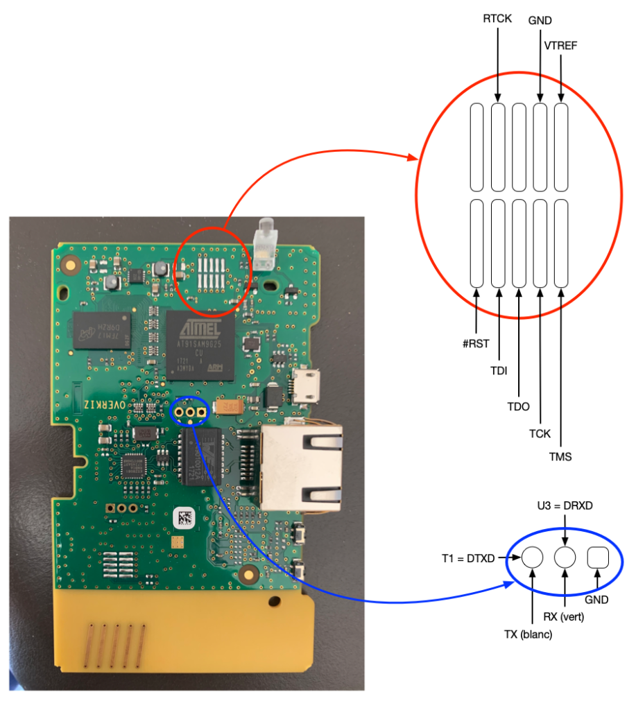
Interacting with the board
From a hardware perspective, no pins, no port, but soldering points! Long story short, here are the useful pins (I will not detail the methodology to identify useful pins and how to use tools, which includes logic analyser, serial-TTL, jtagulator or similar ones, arduino… there are tons of tutorials on the web for that!).
The 2 useful groups of connectors:
Serial console
JTAG port
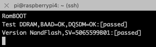
The serial console, as-is, is useless. The firmware has been hardened, and the serial console is disabled in the boot-loader. Upon restart, it is just possible to access the version of bootloader:
Boot trace
We’ll be using the serial console, later.
Using the JTAG port, my first objective was to dump the flash and access the firmware. I did it using 2 techniques:
OpenOCD
Booting a custom uBoot, dumping the flash on a TFTP server
As a JTAG probe, I went (and recommend) to go with a JLink-like (Aliexpress is your friend!). Another perfect alternative which I’ve used for long is the Raspberry PI GPIO ! It might be slower than a dedicated hardware probe, but definitely working and a Swiss army knife.
Daikin Madoka, also known as BRC1H, are new generation of home air-conditioning wired thermostat, that also allow control from mobile phone through Daikin “Madoka Assistant” application.
I got 3 Madoka thermostat installed in my new flat and having them connected to the rest of my Home Automation infrastructure was not optional!
Several options :
Buy a Daikin KNX gateway (3 necessary – one on each internal unit)
Develop a component that could take benefit of BRC1H/Madoka thermostats.
The KNX gateways are expensive (~300€ / unit), and not sure about their good integration/availability – could find very limited information on it – and as I’m still a geek with some technical skills, I decided to go with option #2 – develop a component interacting with Madoka thermostats!