
The Cozytouch is an home automation gateway from the French manufacturer Atlantique/Thermor and also sold under the Sauter brand, depending on selling channel. They’re all identical, both from hardware and software perspective.
The Cozytouch brings the connectivity to various appliances (water boiler, heater…) and the Atlantic cloud (bridge). It allows users to control their appliance from a mobile app available on iOS/Android. Appliances and the bridge are communicating over a closed-source wireless protocol called IOHomeControl operating in the 868mhz band.
The bridge itself, the cloud and the protocols are closed-source and undocumented. The features and data accessible are also very limited. As such, in order to better integrate my water boiler in my home automation, I decided to root the device. 😈
Another option could be hacking the wireless protocol using an RTL/SDR, but if the crypto is well done, it is likely to be a very long way with little results.
Dissassembly & PCB analysis.
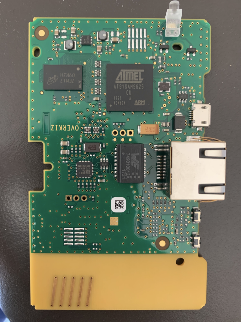
The board is manufacturer/designed by Overkiz, a subsidiary of French manufacturer Somfy.
The board design is pretty simple. It is based on 2 SoC which seems to communicate through a simple UART.
The first SoC, an Atmel AT91SAM9G25, is running the Linux system and in charge of edge-computing feature and communication with the cloud (no wifi – only ethernet). It is surrounded by a 1GB Nand Flash (MX30LF1G18AC) and a 1GB DDR2 RAM module (MT47H64M16NF-25E).
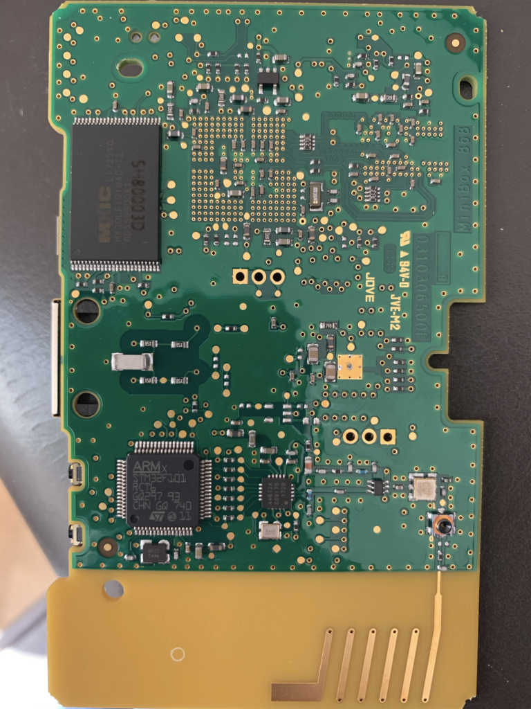
The second SoC, an STMicro ST32, is used exclusively for the radio communication (SDR). It will be found later once the OS is rooted, that this SOC can operate various protocols in various wavelength.
The pure software angle did not provide any way to get in the device. No open port, no upgrade protocol allowing MiTM, encryption made properly… No alternative: go the hard way!
Interacting with the board
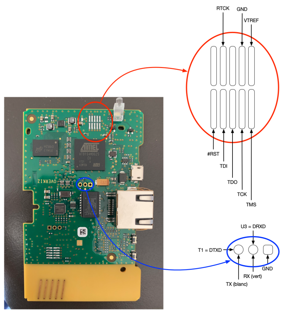
From a hardware perspective, no pins, no port, but soldering points! Long story short, here are the useful pins (I will not detail the methodology to identify useful pins and how to use tools, which includes logic analyser, serial-TTL, jtagulator or similar ones, arduino… there are tons of tutorials on the web for that!).
The 2 useful groups of connectors:
- Serial console
- JTAG port
The serial console, as-is, is useless. The firmware has been hardened, and the serial console is disabled in the boot-loader. Upon restart, it is just possible to access the version of bootloader:
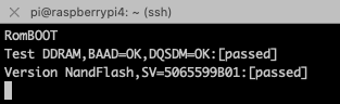
We’ll be using the serial console, later.
Using the JTAG port, my first objective was to dump the flash and access the firmware. I did it using 2 techniques:
- OpenOCD
- Booting a custom uBoot, dumping the flash on a TFTP server
As a JTAG probe, I went (and recommend) to go with a JLink-like (Aliexpress is your friend!). Another perfect alternative which I’ve used for long is the Raspberry PI GPIO ! It might be slower than a dedicated hardware probe, but definitely working and a Swiss army knife.